Understanding electric elements is fundamental to circuit analysis. Electric elements—R, L, C, and power sources—make up electric circuits. These basic ideal electric elements also serve as the building blocks for modeling active components such as transistors. Additionally, parasitic effects in real-world applications can often be described using these basic elements.
Ideal vs. Real
The electric elements used in circuit analysis are idealized. This means each element is mathematically perfect, allowing its behavior to be described using simple mathematical equations. However, in the real world, all electrical devices exhibit non-ideal characteristics and include parasitic effects. For example, a resistor's value may slightly change with variations in voltage or temperature. Moreover, terminal leads and solder joints introduce small inductance and capacitance, which become significant in high-frequency circuits. Even a junction between two different materials can generate noise. In practice, imperfections and approximations are inevitable.
Passive Elements
Resistors, capacitors, and inductors are the basic electric elements in circuit analysis. They are referred to as passive elements because they only consume power and cannot function on their own.
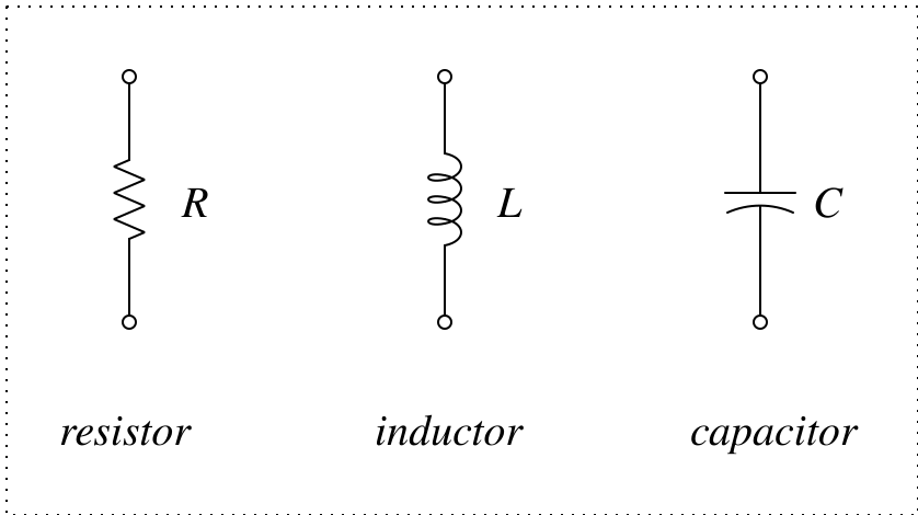
Fig. 1 symbols of the passive elements
Resistors
A resistor follows Ohm's Law, and the unit of resistance (R) is Ohm (Ω).
\[ V = I \cdot R \]
Ohm’s Law seems simple and straightforward, but in complex circuits, it becomes less trivial. Despite its simplicity, Ohm’s Law underlies nearly all circuit behavior. Even in more advanced analysis involving phasors or Laplace transforms, you’ll find yourself applying the same fundamental law.
Capacitors
The behavior of a capacitor is described by the following equation. The unit of capacitance (C) is Farad (F).
\[ i = C \cdot {dv \over dt} \]
If the voltage across a capacitor does not change, no current flows through it. This is why bypass capacitors on circuit boards reduce noise—they shunt AC signals to ground while the DC remains undisturbed.
Inductors
An inductor is, in a way, the reciprocal of a capacitor. The unit of inductance (L) is Henry (H). The equation that describes the behavior of an inductor is:
\[ v = L \cdot {di \over dt} \]
If the current through an inductor remains constant, no voltage appears across it. Inductors readily pass DC but resist changes in current, making them well-suited for passing AC. An inductor behaves as if it has inertia, opposing any sudden changes in current.
Power Sources
Power sources are the components that supply energy to electrical circuits. These can be either voltage or current sources.
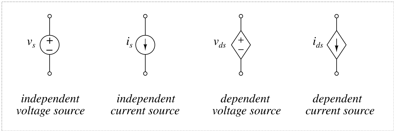
Fig. 2 Symbols of power sources
Ideal voltage sources have zero internal resistance, while ideal current sources have infinite internal resistance.
Independent Sources
An ideal independent source supplies a constant voltage or current to a circuit, regardless of external conditions. To model a functional source like a sine wave, phasor, or impulse, you can annotate the element symbol with the desired function.
Dependent Sources
Dependent sources supply voltage or current based on a quantity from another part of the circuit. The controlling variable is typically a voltage at a specific node or a current through a particular branch.
For the dependent voltage source shown in Fig. 2, the output voltage may be expressed as:
\( v_{ds} = \mu \cdot v_{ref} \) or \( v_{ds} = \rho \cdot i_{ref} \) , where \( \mu \) and \( \rho \) are scaling factors
\( i_{ds} = \alpha \cdot v_{ref} \) or \( i_{ds} = \beta \cdot i_{ref} \) , where \( \alpha \) and \( \beta \) are scaling factors
Modeling
Modeling in circuit analysis simply means describing a real-world circuit component using ideal circuit elements. For example, active components such as transistors or diodes can be modeled with basic circuit elements. Parasitic effects on a transmission line in high-frequency applications can also be modeled using ideal capacitors and resistors.
Active Elements
Active elements—such as transistors and diodes—are circuit elements that actively control the current or voltage in a circuit. These active elements can be modeled using ideal passive elements and power sources. Note that a model of an active element always includes at least one power source.
For example, the following shows the simplest behavioral mathematical model of an N-type MOSFET (Metal-Oxide-Semiconductor Field-Effect Transistor).
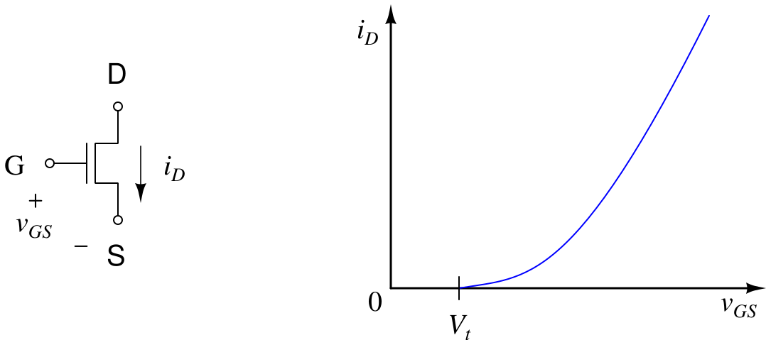
Fig. 3. Ideal characteristic of an N-type FET
The following simple yet reliable mathematical equation describes NMOS behavior:
\[i_D = K(v_{GS}-V_t)^2\]
This behavior can be modeled using fundamental circuit elements as shown below.
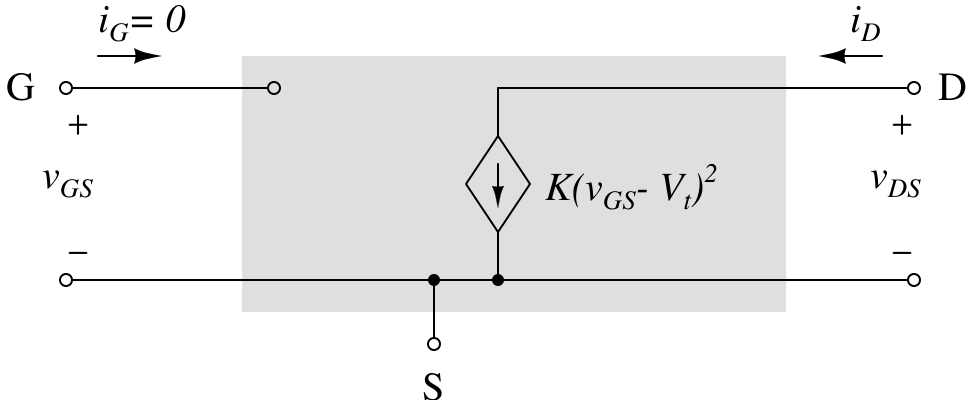
Fig. 4. A simple large-signal model of an N-type MOSFET
As shown in Fig. 4, the input and output resistance in this simple model is infinite—remember, the internal resistance of any ideal current source is infinite. However, in an actual MOSFET, these resistances have finite values.
The model in Fig. 4 is a large-signal model, which means it applies to both DC and AC analysis. In contrast, a small-signal model is used only for small-signal analysis under the assumption that the DC bias has already been established. For example, you would use a small-signal model to calculate the gain of an amplifier.
In a small-signal model, DC factors are removed. Thus, the threshold voltage \(V_t\) in the equation—depicted in Fig. 3—does not need to be included anymore.
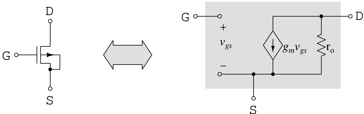
Fig. 5. A simple small-signal model of an NMOS
The actual output impedance of a MOS transistor, \(r_o\), is not infinite—it typically ranges from a few M\(\Omega\) to hundreds of M\(\Omega\). You should include it even in hand calculations. While the bulk terminal (B) exists in a real MOSFET, it is often assumed to be connected to the source (S) terminal, as shown in Fig. 5. Parasitic elements exist between terminals, but they are usually only significant in high-frequency or high-accuracy applications.
The BSIM (Berkeley Short-channel IGFET Model) is intended for integrated circuit design. It provides extremely detailed MOSFET models at various levels. If we were to draw the BSIM model as a schematic, it would resemble something like Fig. 6.
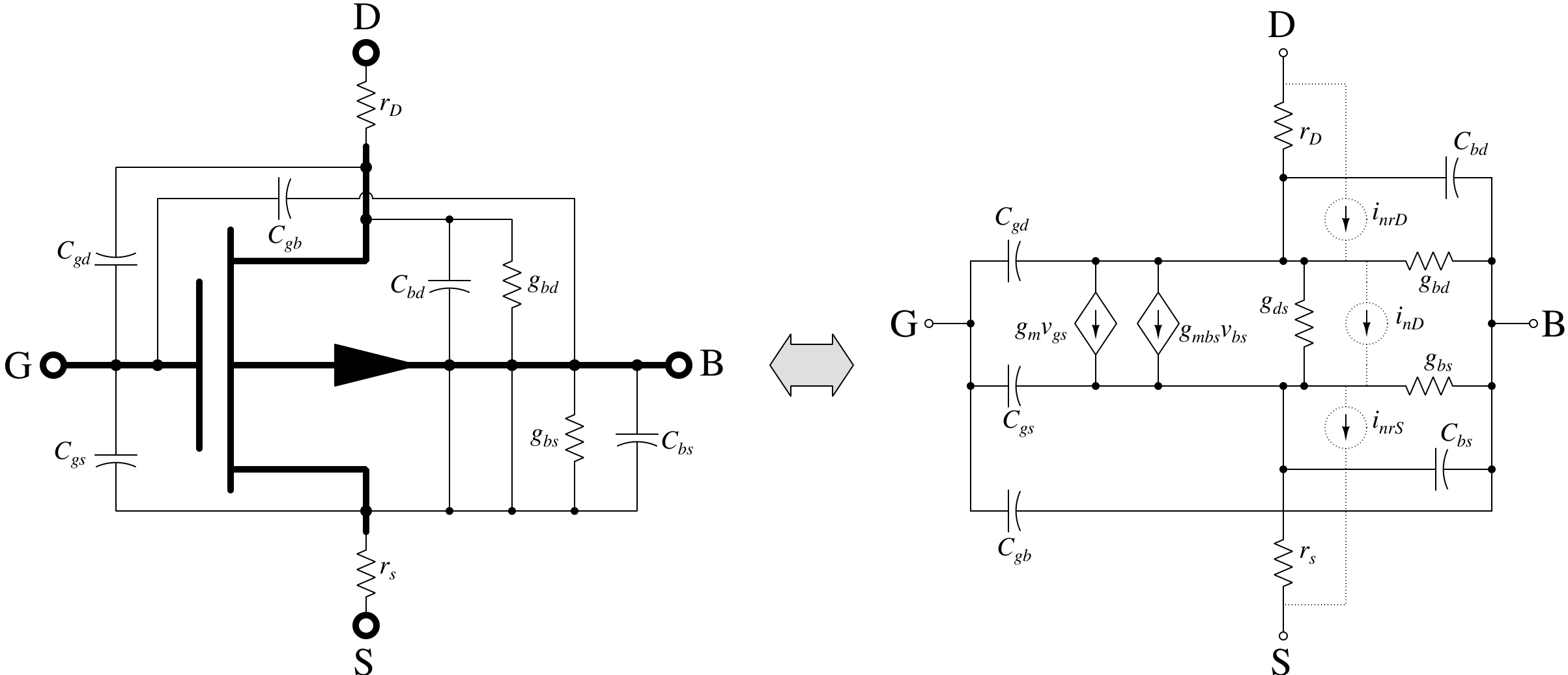
Fig. 6. A small-signal model of an NMOS with parasitics
These models are usually provided by others or by the part suppliers. Your only task is to include them in your simulation.
Manual Analysis
Once you understand the fundamental physical laws governing circuit elements, you can analyze circuits mathematically. You may need mathematical skills beyond basic algebra—such as linear algebra, phasor analysis in the complex domain, Laplace transforms, Fourier transforms, and more. Even if you're excellent at math, manual analysis becomes extremely time-consuming as the circuit complexity increases.
However, if you properly divide the circuit into functional blocks, it is possible to obtain reasonably accurate results. In fact, there are many circuit simulators available for free. When used properly, they can provide accurate results much faster than manual calculations.
Nevertheless, manual analysis remains essential. It gives you valuable insights into the circuit you're working on. Often, you won’t even know what to simulate until you understand the target circuit through manual analysis.
Circuit simulators
SPICE (Simulation Program with Integrated Circuit Emphasis) is the most commonly used simulator among analog circuit designers. If you're designing digital integrated circuits, HDL tools are more suitable for design and simulation. However, for analog or mixed-signal circuits (those combining analog and digital parts), SPICE is your go-to tool.
At the system level, if your design includes some analog blocks, you can model the analog part using Verilog-A. This is typically done for verifying the interface between blocks, rather than for precise analog behavior.
There are many options for analog and mixed-signal simulation tools. My first choice would be HSPICE, but it’s far too expensive for a hobbyist like myself. My next best option is NGSPICE. It’s free, reliable, and widely used. Personally, I believe the specific simulator matters less as long as you're using accurate SPICE models.
NGSPICE is compatible with most SPICE model formats—including those from HSPICE, PSPICE, and others. This is a huge advantage, as most electronic component manufacturers provide models in HSPICE or PSPICE formats, which are industry standards.
Post your comment